[Download code for the project: GitHub]
In this post we will build a simple virtual reality (VR) app that allows the user to explore a virtual environment by moving the Android device. The app will use accelerometer and gyroscope sensors to determine the device’s orientation.
The output of the project on a Nexus 5 is shown below. The user can rotate the phone to explore the virtual environment in all directions. Double-tapping the screen resets the display to point to the front of the scene.
On some devices, we may observe jitter in the display due to noise in the gyroscope sensor’s output.
In the previous tutorial, we used Assimp to load a 3D model described in the OBJ format. Here we use Assimp to load a 3D model corresponding to the virtual environment displayed above.
As mentioned before, our approach is largely based on native C++ code in Android and there are a few pre-requisites to understand the project. Kindly go through earlier tutorials to have a better understanding of this post.
Contents
Get the code
This project is available on GitHub. You can find more instructions to compile the project here.
The project will run on Android devices that have both a gyroscope and an accelerometer. It also requires devices with ABI armeabi-v7a. If your device supports a different ABI, then please get in touch with me for the required libraries.
Code overview
This project is similar to the previous project, with addition of few files and simplification of few files. We mention the files that are different than the previous project (paths are relative to <project_path>/app/src/main):
- java/com.anandmuralidhar.simplevrandroid/SimpleVRActivity.java: It contains the only activity of the project and is similar to AssimpActivity.java from the previous project except for instantiation of a
SensorClass. It’s JNI calls are implemented in simpleVRActivity.cpp. - java/com.anandmuralidhar.simplevrandroid/GestureClass.java: It is a simplified version of a file with the same name in an earlier tutorial. We have only retained the double-tap gesture detector and deleted the rest.
- java/com.anandmuralidhar.simplevrandroid/SensorClass.java: This file implements methods to read data from accelerometer and gyroscope sensors. Its JNI calls are implemented in sensorClass.cpp.
- jni/nativeCode/simpleVRClass/simpleVRClass.cpp: It is based on modelAssimp.cpp. The only changes are that this file loads a 3D model corresponding to a virtual world and implements methods to translate sensor readings to a MVP matrix.
- assets/ourWorld: The directory contains OBJ, MTL, and JPEG files that define a virtual environment.
Creating a virtual world
Here are pictures of our virtual world from a distance:
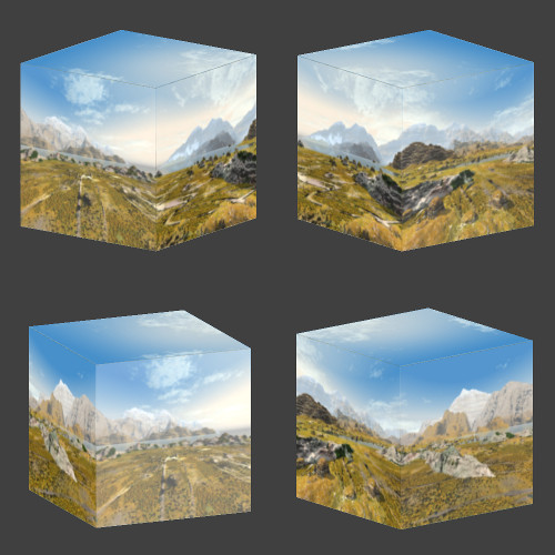 It’s just a cube! 🙂 We have created a cube and chosen an image as the texture for each of its six faces. These six images form a so-called “skybox” in OpenGL. The pictures are clicked or created in such a way that if the camera is placed inside the cube, then it creates the illusion of being in an virtual environment. This trick is used in many games that have an artificial environment as the backdrop when a player moves around.
In the constructor of SimpleVRClass in simpleVRClass.cpp, we place the GLES camera and the center of the OBJ (the cube, ourWorld.obj) at the origin in worldspace:
// create MyGLCamera object and place camera in center of the world, zPosition=0
myGLCamera = new MyGLCamera(45, 0);
float pos[]={0.,0.,0.,0.,0.,0.}; // center of cube (ourWorld) coincides with center of world
std::copy(&pos[0], &pos[5], std::back_inserter(modelDefaultPosition));
myGLCamera->SetModelPosition(modelDefaultPosition);
The model is never translated in this project, it is only rotated along with change in device orientation to create an illusion that the user is exploring the environment.
We extract the OBJ corresponding to the cube, ourWorld.obj, in SimpleVRClass::PerformGLInits. We also extract its companion MTL file and the six images corresponding to textures for faces.
bool isFilesPresent  =
    gHelperObject->ExtractAssetReturnFilename("ourWorld/ourWorld.obj", objFilename) &&
    gHelperObject->ExtractAssetReturnFilename("ourWorld/ourWorld.mtl", mtlFilename) &&
    gHelperObject->ExtractAssetReturnFilename("ourWorld/deception_pass_bk.jpg", texFilename) &&
    gHelperObject->ExtractAssetReturnFilename("ourWorld/deception_pass_dn.jpg", texFilename) &&
    gHelperObject->ExtractAssetReturnFilename("ourWorld/deception_pass_ft.jpg", texFilename) &&
    gHelperObject->ExtractAssetReturnFilename("ourWorld/deception_pass_lf.jpg", texFilename) &&
    gHelperObject->ExtractAssetReturnFilename("ourWorld/deception_pass_rt.jpg", texFilename) &&
    gHelperObject->ExtractAssetReturnFilename("ourWorld/deception_pass_up.jpg", texFilename);
We have seen in the previous post how to extract 3D models from the assets directory and render it with Assimp.
Note: In OpenGL, such a virtual environment is usually rendered with a cubemap. A cubemap is effectively the same as a textured cube since it loads six images corresponding to the faces of a cube. However we do not want to introduce a new concept when we can reuse tools that we discussed in previous tutorials. Moreover, a cubemap is useful when we want to model realistic reflections on objects in the scene.
Determining device orientation
We do not allow the user to move the environment using touch gestures. Instead we track the device’s orientation and render the appropriate portion of the virtual environment. This creates an immersive experience for the user since moving the device creates an illusion of exploring the virtual environment. Also we only model the rotation of the device in all directions, but do not model translation of the device. Hence a user can stand in a place and rotate the device to view the virtual environment in all directions, but the user cannot step in a direction to move closer to objects in the scene.
We determine the device’s orientation using two sensors; accelerometer and gyroscope. The accelerometer measures acceleration applied to the device and the gyroscope measures the rate of rotation around the device’s three axes. The acceleration applied to the device includes acceleration due to gravity. We extract gravity from the accelerometer’s output using a filter. The gravity vector tells us the orientation of the device with respect to the ground. We use the gravity vector to orient the virtual environment so that the bottom of the displayed virtual environment is always parallel to the ground. We track the rotation of the phone using the gyroscope. The gyroscope’s output is integrated and converted to a rotation that is applied to the model describing the virtual world. This allows us to appropriately move the virtual environment along with a change in the device rotation.
Let’s get into details of implementation. In SensorClass.java, we implement methods of the SensorEventListener. In constructor of SensorClass, we check if the device has a gyroscope and an accelerator sensor:
public SensorClass(Activity mainActivity, View view) {

    mSensorManager = (SensorManager) mainActivity.getSystemService(Context.SENSOR_SERVICE);

    // fetch gyro and accel sensors
    mGyro = mSensorManager.getDefaultSensor(Sensor.TYPE_GYROSCOPE);
    mAccel = mSensorManager.getDefaultSensor(Sensor.TYPE_ACCELEROMETER);

    // if either sensor is not available, app will exit
    isSensorsAvailable = (mGyro != null) && (mAccel != null);
    mView= view;

    // initialize gravity vector to 0 before starting to filter inputs
    gravity[0] = 0.0f;
    gravity[1] = 0.0f;
    gravity[2] = 0.0f;
}
An object mSensorObject of type SensorClass is instantiated in onCreate of SimpleVRActivity. If either gyroscope or accelerometer sensors is not available in the device, then the app will exit.
Listeners to sensors are registered in RegisterSensors in SensorClass:
isGyroSensorAvailable = mSensorManager.registerListener(this, mGyro,
        SensorManager.SENSOR_DELAY_GAME);

isAccelSensorAvailable = mSensorManager.registerListener(this, mAccel,
        SensorManager.SENSOR_DELAY_GAME);
This method is called in onResume of SimpleVRActivity and the app will exit if we fail to register a listener for either sensor.
Once the listeners are registered, we access the sensor’s raw data in onSensorChanged. In onSensorChanged, we account for the device’s rotation and rearrange the sensor’s raw data before processing it further.
The sensor coordinate system in Android can be confusing unless you are able to visualize it in 3D space. As shown in the image here, the 3 axes of the sensor coordinate system are defined with respect to the natural orientation of the device. On most devices, the natural orientation is portrait but it can be landscape in some tablets. We find the current orientation of the device with respect to its natural orientation with getRotation:
deviceRotation = mView.getDisplay().getRotation();
Then we rearrange the sensor’s raw data in event.values so that remainder of the code is oblivious to the change in device orientation. As en example, consider the case when device is rotated 90 degrees in counter-clockwise direction with respect to its natural orientaion:
switch(deviceRotation) {
    ...
    case Surface.ROTATION_90:
        eventValues[0] = -event.values[1];
        eventValues[1] = event.values[0];
        eventValues[2] = event.values[2];
        break;
    ...
}
If you compare the above scenario with this figure, then you can see that in this orientation X axis is pointing up, Y axis is pointing to the left, and Z axis is unchanged. Hence event.values[0], which is readings from X axis of sensor, is copied to eventValues[1] corresponding to Y axis in this orientation. event.values[1], readings from Y axis of sensor, is negated and copied to eventValues[0] that corresponds to X axis in this orientation. Give yourself a few moments and think through it.
Next we separately process the data depending on whether it is from the accelerometer or the gyroscope.
switch (event.sensor.getType()) {

    case Sensor.TYPE_ACCELEROMETER:
        CalculateGravityFromAccelerometer(eventValues);
        SendGravityToNative(gravity[0], gravity[1], gravity[2]);
        break;

    case Sensor.TYPE_GYROSCOPE:
        CalculateRotationVectorFromGyro(event, eventValues);
        SendGyroQuatToNative(gyroQuaternion[0], gyroQuaternion[1], gyroQuaternion[2],
                gyroQuaternion[3]);
        break;
}
In CalculateGravityFromAccelerometer, we low-pass filter the accelerometer data as suggested here to extract the gravity vector from it:
gravity[0] = ACCEL_ALPHA * gravity[0] + (1 - ACCEL_ALPHA) * accel[0];
gravity[1] = ACCEL_ALPHA * gravity[1] + (1 - ACCEL_ALPHA) * accel[1];
gravity[2] = ACCEL_ALPHA * gravity[2] + (1 - ACCEL_ALPHA) * accel[2];
We send the gravity vector to native code where it is used to orient the virtual scene as mentioned below.
In CalculateRotationVectorFromGyro, we convert the gyroscope’s data to a quaternion by integrating it as suggested here. The only change in our function is that we pass the quaternion to native code for further processing by GLM. Hence our representation of the quaternion matches the format used by GLM.
Using sensor data in native code
The JNI calls from SensorClass are implemented in sensorClass.cpp and they simply call methods of SimpleVRClass that process the sensor data. The gravity vector is sent to SimpleVRClass::UpdateGravity where it is saved in a private variable.
void SimpleVRClass::UpdateGravity(float gx, float gy, float gz) {

    gravityMutex.try_lock();
    gravity[0] = gx;
    gravity[1] = gy;
    gravity[2] = gz;
    gravityMutex.unlock();
    return;
}
We use a mutex since the gravity variable is accessed in the GLES thread in SimpleVRClass::Render to update the MVP matrix.
glm::mat4 mvpMat = myGLCamera->GetMVPAlignedWithGravity(gravity);
Let’s look at GetMVPAlignedWithGravity, which is a new addition to MyGLCamera. First we determine the current position of Y axis in the scene since Y axis points in the upward direction to begin with as shown in this figure:
// extract 3x3 rotation mat from model mat
glm::mat3 currentRotationMat = glm::mat3(modelMat);
// in every device, Y axis is pointing upwards before applying rotations
// check the current position of Y axis after rotating it
glm::vec3 sceneUpVector = currentRotationMat * glm::vec3(0.0, 1.0, 0.0);
sceneUpVector = glm::normalize(sceneUpVector);
Then we normalize the gravity vector and determine the angle between gravity vector and the sceneUpVector. We also determine the axis that is perpendicular to both sceneUpVector and gravityVector
// find the angle between sceneUpVector and gravity vector
float cosTheta = fmax(fmin(glm::dot(sceneUpVector, gravityVector), 1.), -1.);
float rotationAngle = acos(cosTheta);
glm::vec3 rotationAxis = glm::cross(sceneUpVector, gravityVector);
rotationAxis = glm::normalize(rotationAxis);
Then using functions that are familiar to us from previous posts, we construct a quaternion rotation matrix that can align sceneUpVector with gravityVector:
glm::quat gravityRotationQuat = glm::angleAxis(rotationAngle, rotationAxis);
glm::mat4 gravityRotationMat = glm::toMat4(gravityRotationQuat);
The final step is easy, we add an extra rotation with gravityRotationMat so that the model (the virtual environment) is aligned with respect to the gravity vector:
glm::mat4 currentModelMat = modelMat;
glm::mat3 correctedRotationMat = glm::mat3(gravityRotationMat) * currentRotationMat;
for(int r=0;r<3;r++){
    for(int c=0;c<3;c++){
        currentModelMat[c][r] = correctedRotationMat[c][r];
    }
}

glm::mat4 newMvpMat = projectionViewMat * currentModelMat;
Back to SimpleVRClass; in UpdateRotation we convert the input quaternion derived from gyroscope's inputs to a rotation matrix using GLM's inbuilt functions:
glm::quat gyroQuaternion(gyroQuatW, gyroQuatX, gyroQuatY, gyroQuatZ);
glm::mat4 gyroRotationGLMMat = glm::toMat4(gyroQuaternion);
Now note that the virtual scene must be rotated in a direction that is opposite to rotation of the device. So we need to invert the rotation matrix derived above. But transpose of a rotation matrix is equal to its inverse:
gyroRotationGLMMat = glm::transpose(gyroRotationGLMMat);
This matrix is used to update rotationMat in MyGLCamera by passing it to AddDeltaRotation under a mutex:
gyroMutex.try_lock();
myGLCamera->AddDeltaRotation(gyroRotationGLMMat);
gyroMutex.unlock();
We need a mutex since AddDeltaRotation modifies the modelMat in MyGLCamera and modelMat is accessed by the GLES rendering thread in SimpleVRClass::Render. MyGLCamera::AddDeltaRotation is very simple:
rotateMat = rotateMat * deltaRotationMat;
modelMat    = translateMat * rotateMat;
It accumulates the change in rotation by modifying rotateMat and subsequently modelMat. The updated modelMat will be used in SimpleVRClass::Render to derive the new MVP matrix as described above.
Effects of noise in sensors
In some devices, you may notice that this project's display is very jittery or the display does not move as expected when you rotate the phone. On most occasions this is because of noise in the gyroscope's data. The gyroscope is not the best sensor for tracking change in orientation. The rotation vector sensor in Android is a better alternative since its output is derived by fusing data from multiple sensors. Similarly the accelerometer is not the best sensor to determine gravity, the gravity sensor is a better alternative.
Since rotation and gravity sensors are not available on many devices, we chose to use sensors that are present on most devices. We can rewrite the code to use better sensors if available, but that will add unnecessary complexity to a simple project.