[Download code for the project: GitHub]
In this post we explore an important concept in OpenGL ES; the Model–View–Projection or MVP matrix. We will understand :
- The three matrices that comprise a MVP matrix — Model, View, and Projection.
- How to use the OpenGL Mathematics (GLM) library to generate the MVP matrix.
- How to move a colored cube with touch gestures.
Here’s a short video of the output on a Nexus 5, with visual feedback enabled to indicate touch gestures:
Contents
Get the code
This project is available on GitHub. Refer to this link for more details on how to import the project.
Code overview
In previous tutorial posts, we showed how to create GLES context in Java, load shaders in native code, and render with native calls. We will continue with that approach that mainly relies on native code while leveraging the benefits of Java.
Many of the files in this project are similar to (or even same as) files in previous tutorials. We only mention new files (all paths are relative to <project_path>/app/src/main):
- com.anandmuralidhar.cubeandroid/CubeActivity.java: As before, there is one Java activity in the application as defined in this file;
CubeActivity. - com.anandmuralidhar.cubeandroid/GestureClass.java: It contains a class,
GestureClass, that is responsible for handling touch gestures and its JNI calls are implemented in jni/jniCalls/gestureClass.cpp. - jni/nativeCode/common/myGLCamera.cpp: It contains implementation of a “camera” that we use in GLES to view the world.
- jni/nativeCode/common/myGLM.h: A file that includes GLM headers.
- jni/nativeCode/cube/myCube.cpp: Implements a class
MyCubethat contains methods to create and render a colored cube. - assets/shaders/cubeMVP.vsh and cubeMVP.fsh: Shaders that use the MVP matrix to move a 3D model.
Constructing MVP matrix with GLM
If you are not familiar with a matrix, then you should spend time with a linear algebra book, watch a set of videos on the topic, or at least understand basics of matrices before proceeding further. The following brief introduction to MVP relies on the knowledge of matrices and is inspired by discussions in the excellent Red book.
In the previous tutorial post, we displayed a triangle by sending its vertices to the vertex shader. This approach has two problems. First, to animate an object we need to compute new positions for all vertices and update data in the vertex buffer for a rendering call. Can you imagine the computational load if you want to animate a 3D model with thousands of vertices? We will probably not be able to animate and render the model in real-time or will consume most of the CPU’s computational resources for this. The second problem is a variant of the first; when we change the orientation of the phone from portrait to landscape, then the triangle’s shape changes and its height gets squished while its base gets lengthened. This is because the triangle’s vertices have fixed coordinates irrespective of the device orientation and do not preserve its shape.
Now let us consider a different approach towards rendering the triangle that is based on a real-world analogy. If we were planning to take a picture of the same triangle with a camera, then we would follow these steps:
- Arrange the triangle in the scene in the required position.
- Setup the camera on a tripod and point it at the scene.
- Choose a lens for the camera with an appropriate field-of-view (FOV) and choose an aspect ratio for the picture.
In order to simulate animation of the triangle by taking a series of pictures, we simply change the triangle’s position for each picture. Also to simulate change in the device orientation we rotate the camera by 90 degrees and take a picture, yet the triangle’s shape will remain unchanged. The above three steps are mathematically modeled as the Model, View, and Projection transformations respectively.
Model matrix
We begin with specifying vertices of a model (maybe our triangle) in a space referred to as model space. In model space, vertices are specified with respect the model’s origin. For example, we can define the triangle’s vertices as shown in this array with the origin inside the triangle. To place the triangle in the world, we need to move the triangle’s vertices to a new position by multiplying them with a matrix. This matrix transforms the triangle’s vertices from model space to world space (but preserves its shape) and is referred to as the Model matrix.
In our discussions, we will restrict the Model matrix to model two types of movements; translation of the object and rotation of the object. We ignore scaling of the object since it deforms the object’s shape and we are only concerned with rigid objects. To specify a rigid object’s position in the world, we need to specify six parameters corresponding to its six-degrees-of-freedom. These correspond to translations along X, Y, and Z axes, and three angles of rotation about each of these axes. The first three parameters determine a Translation matrix and the next three determine a Rotation matrix. The Model matrix is defined as:
Model = Translation * Rotation;
Hence we first rotate an object and then move it to the required position in world space.
Homogeneous coordinates
Before we mathematically construct the Model matrix, we introduce the notion of homogeneous coordinates that is critical in computer graphics. It is a simple concept; if a 3D vertex has coordinates (x,y,z), then we convert it to a homogeneous coordinate (x,y,z,w) with w=1.0. This may seem absurd without understanding the theory behind it, but this simple change will allow us to reduce all calculations in this section to matrix multiplications.
Translation matrix
Now we use the GLM library to construct the Model matrix. We start with the simplest one; the Translation matrix:
Translation = glm::mat4(1, 0, 0, 0,                 // column0
                        0, 1, 0, 0,	            // column1
                        0, 0, 1, 0,	            // column2
                        deltaX, deltaY, deltaZ, 1); // column3
GLM specifies matrices in row-major order. Hence the above constructs a matrix that actually looks like
Translation =

If we have a homogeneous coordinate defined as a 4-tuple in GLM, glm::vec4(x, y, z, 1.), then multiplying it with the Translation matrix moves it deltaX, deltaY, and deltaZ units along the three axes to glm::vec4(x + deltaX, y + deltaY, z + deltaZ, 1.).
Rotation matrix
The Rotation matrix is a tad more involved to compute and we describe any rotation with a quaternion. We will not explore quaternions in detail and point you to other references such as this. For now it suffices to know that a quaternion represents rotation by an angle around an axis in the 3D space. Any sequence of rotations can be reduced to a single quaternion.
The angles of rotation specifying a rigid object’s orientation are commonly referred to as pitch, yaw, and roll, and can be converted to a quaternion with GLM:
modelQuaternion = glm::quat(pitchAngle, yawAngle, rollAngle);
The modelQuaternion can be converted to a 4×4 matrix with another GLM function to get the Rotation matrix:
Rotation = glm::toMat4(modelQuaternion);
Finally to get the Model matrix, we multiple the Translation and Rotation matrices as shown here.
View matrix
Next let’s place a camera in the world. We do it a little differently than the previous case. We change the origin to the camera’s position and calculate the model’s vertices with respect to the camera’s position. This space is referred to as camera space, eye space, or view space. We multiply the model’s vertices in world space with the View matrix to calculate positions of vertices in camera space. The View matrix captures the position and direction of the camera and orients it appropriately. There is a function in GLM that takes these inputs and constructs the View matrix:
View = glm::lookAt(cameraPosition,  // glm::vec3, camera location in world space
                   cameraCenter,    // glm::vec3, where is the camera looking
                   cameraUpVector); // glm::vec3, direction of up vector
The first two inputs tell the function to place the camera at cameraPosition and point it towards cameraCenter. The last input cameraUpVector selects the direction in which the camera is pointed, i.e., up, upside-down, sideways, etc. In most cases, we choose cameraUpVector = glm::vec3(0, 1., 0); to indicate that the camera is pointing up in the direction of Y axis.
Projection matrix
If you are in a room, move to a corner of the room and look at lines formed by intersection of the ceiling with the wall. Closely observe two such parallel lines and you will notice that these two lines appear to be moving closer as they recede away from you. In fact if your room had infinite length, then these lines will appear to meet at a distance! This is due to perspective projection of the scene in our eyes. Perspective projection makes farther objects appear smaller in size (called fore-shortening) and is modeled with the Projection matrix.
The Projection matrix captures the world inside a viewing frustum. A frustum is a pyramid whose top is chopped off with a plane parallel to its base. The camera is assumed to be placed at the apex of the pyramid and is pointing at the base. The frustum is defined by the near and far planes that define its clipping planes and by the field-of-view that effectively determines its height. All objects inside the viewing frustum are projected towards the camera in the apex of the frustum. To take a picture of the scene inside the frustum, we look at the projections on the near plane. It is easy to see that objects closer to the near plane appear larger than objects closer to the far plane inside the frustum. 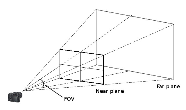
Once again, GLM has a function that generates a Projection matrix with the required parameters:
Projection = glm::perspective(FOV,                  // vertical field-of-view
                              aspectRatio,          // aspect ratio of the camera
                              nearPlaneDistance,    // distance between camera and near plane
                              farPlaneDistance);    // distance between camera and far plane
MVP matrix
The final step to construct the MVP matrix is easy, all ingredients are in place:
MVP = Projection * View * Model;
The MVP matrix combines all the transformations into a single 4×4 matrix. The MVP matrix multiplies homogeneous coordinates that describe a 3D model’s vertices. As a result, the coordinates move through various spaces to finally obtain clip coordinates as shown in the figure below.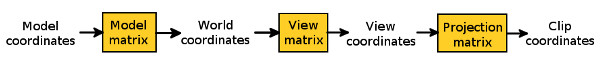 We do not discuss clip coordinates in this tutorial. They are further processed by GLES to derive the final image after accounting for viewport dimensions.
Now you may be able to appreciate the power of homogeneous coordinates that allowed us to represent any complex transformation of a 3D object with multiplication by a 4×4 matrix. This MVP matrix is computed in native code for every frame and sent to GLSL ES shaders for multiplying with vertex positions. This simple operation is powerful enough to recreate any transformation of the 3D object. In most cases, the View and Projection matrices are computed only once while the Model matrix is computed every time the object’s position needs to be changed.
MVP in myGLCamera.cpp
Let’s see how to generate the MVP matrix in our project. We will focus on myGLCamera.cpp since it contains the MyGLCamera class to simulates a camera for rendering the GLES surface.
In the class constructor, we place the camera at a fixed position in the Z axis and point it at the negative Z axis to construct the View matrix:
glm::vec3 cameraPosition = glm::vec3(0, 0, zPosition);
viewMat = glm::lookAt(cameraPosition,        // Camera location in World Space
                      glm::vec3(0, 0, -1),   // direction in which camera it is pointed
                      glm::vec3(0, 1, 0));   // camera is pointing up
We save the other input parameters like nearPlaneDistance, farPlaneDistance, FOV to construct the Projection matrix later. Since the Projection matrix is not yet known, MVP is initialized to identity matrix:
mvpMat = glm::mat4(1.0f); // projection is not known -> initialize MVP to identity
In the function SetAspectRatio, the aspect ratio is used to construct the Projection matrix:
void MyGLCamera::SetAspectRatio(float aspect) {

    glm::mat4 projectionMat;
    projectionMat = glm::perspective(FOV * float(M_PI / 180), // camera's field-of-view
                                     aspect,                  // camera's aspect ratio
                                     nearPlaneDistance,       // distance to the near plane
                                     farPlaneDistance);       // distance to the far plane
    projectionViewMat = projectionMat * viewMat;
    ComputeMVPMatrix();

}
Since Projection and View matrices do not change for each frame, we combine them together into projectionViewMat. We often call ComputeMVPMatrix in this class’s methods to recompute the MVP matrix:
void MyGLCamera::ComputeMVPMatrix() {

    translateMat = glm::mat4(1, 0, 0, 0,                  // col0
                             0, 1, 0, 0,	          // col1
                             0, 0, 1, 0,	          // col2
                             deltaX, deltaY, deltaZ, 1);  // col3

    modelMat    = translateMat * rotateMat;
    mvpMat      = projectionViewMat * modelMat;
}
We assume that translation coordinates deltaX, deltaY, deltaZ, and the Rotation matrix, rotateMat, are correctly initialized before calling this function. Both the position and the orientation of the model can be changed by passing new values for six-degrees-of-freedom to SetModelPosition. This function uses GLM methods that we discussed earlier to convert pitch, yaw, and roll angles to a quaternion, and generate a rotation matrix from it.
We have defined three functions, ScaleModel, RotateModel and TranslateModel, to help in converting touch gestures to a corresponding MVP matrix. ScaleModel changes the perceived size of an object by moving it closer to the screen or by pushing it further away on the Z axis. Similarly TranslateModel converts distance traversed by a touch gesture on the screen to a change in position of the 3D model on the X and Y axes. RotateModel is little trickier since it converts a drag on the screen to a quaternion for rotating the 3D model. The generated quaternion depends on both the starting location and ending location of the drag gesture on the device’s screen. We have briefly mentioned the algorithm used to determine the quaternion in comments in the function and will skip a detailed discussion.
In order to aid in debugging, we have added a function PrintGLMMat in misc.cpp to print the contents of a glm::mat4 object.
Create a colored cube
We display a 3D cube in this project instead of a 2D triangle to show the potential of the MVP matrix. myCube.cpp contains implementation of the MyCube class that renders a cube on the screen. In the class’ constructor, we instantiate an object of type MyGLCamera and set the default position of the cube. If a user double-taps the screen, then the cube’s position is reset to this default position.
PerformGLInits is very similar to the corresponding function for the Triangle class in the previous post. The call to MyGLInits in myGLFunctions.cpp calls a few extra GLES functions:
// Enable depth test
glEnable(GL_DEPTH_TEST);
// Accept fragment if it closer to the camera than the former one
glDepthFunc(GL_LEQUAL);
Since we are displaying a 3D object in this project, we enable the depth buffer and ensure that if two faces overlap while displaying them, then we display the face that is closer to the camera. For example, we want to display front faces of the cube that are visible to us and not the back faces that are hidden from us.
In PerformGLInits, we specify vertices of the cube along with a unique color for each of the six faces. Then we load the shaders cubeMVP.vsh and cubeMVP.fsh and get the locations of attribute variables. There is an addition when compared to the Triangle class:
mvpLocation = GetUniformLocation(shaderProgramID, "mvpMat");
GetUniformLocation in myShader.cpp fetches the location of a uniform variable from the shader, in this case location of the variable corresponding to the MVP matrix in the shader. A variable defined with the uniform qualifier remains constant across all vertices passed to the shader. It is a useful qualifier for variables such as mvpMat that are passed once every rendering call and are updated, if necessary, in the next call. In contrast, the attribute qualifier in the shader is used for variables that are updated for every vertex. We briefly digress to look at the relevant portion of the vertex shader cubeMVP.vsh:
...
uniform     mat4 mvpMat;

void main()
{
    gl_Position     = mvpMat * vec4(vertexPosition, 1.0);
    fragmentColor   = vertexColor;
}
The shader is almost similar to colorTriangle.vsh except for mvpMat that multiplies the vertices after converting them to homogeneous coordinates. cubeMVP.fsh is same as the previously discussed shader colorTriangle.fsh.
Back to the MyCube class; in the RenderCube function, we update the value of the MVP matrix for each frame:
glm::mat4 mvpMat = myGLCamera->GetMVP();
glUniformMatrix4fv(MVPLocation, 1, GL_FALSE, (const GLfloat *) &mvpMat);
glUniformMatrix4fv updates the contents of the unifom variable, mvpMat, in cubeMVP.vsh.
It is very easy to transfer a GLM mat4 to GLSL ES shader and use it as-is! Similarly we can also pass glm::vec3 to a vec3 in the shader. We effectively view GLM as an extension of GLSL to calculate uniform variables in native code. Since GLM can be ported across platforms, the same code can be potentially reused in various mobile apps (iOS, Android) or even in a desktop app.
To render the cube, we need to specify the correct number of vertices in the call to glDrawArrays:
glDrawArrays(GL_TRIANGLES, 0, 36); // cube has 12 triangles = 36 vertices.
Remember that SetViewport is called once the GLES surface is created in Java (see this). In this function, we have access to the width and height of the GLES surface, and set the aspect ratio in the myGLCamera object.
myGLCamera->SetAspectRatio((float) width / height);
This allows the myGLCamera object to calculate the Projection matrix as mentioned here.
Remaining functions in the MyCube class are responsible for handling the touch gestures. They simply call the corresponding function in MyGLCamera to calculate the MVP matrix.
Note: In PerformGLInits, we specify 36 vertices corresponding to 12 triangles that define a cube. But you may notice that a cube actually has only 8 vertices and each vertex is repeated many times in the list. This is clearly inefficient and there is a better approach to specify repeated vertices in GLES using an index buffer. This is covered in a subsequent tutorial.
Converting touch gestures to MVP
GestureClass.java implements a bunch of classes that are responsible for detecting various touch gestures. These are fairly standard approaches in Android and there are good tutorials on this topic available elsewhere. We will briefly discuss each of them and mention references that discuss them in more detail.
We support four gestures in this project:
- Double-tap: reset the Cube’s position.
- Two-finger drag: move the Cube on the screen.
- Pinch-and-zoom: scale the Cube to make it appear bigger or smaller.
- One-finger-drag: rotate the Cube.
MyTapScrollListener class extends the GestureDetector.SimpleOnGestureListener interface. We override the onDoubleTap and onScroll methods to detect double tap and to track scrolling by two fingers. Both the methods call native functions that convert the gesture to a MVP matrix. Note that onScroll checks the flag mTwoFingerPointerId before making a JNI call. This flag indicates if one or two fingers are being used for scrolling. This tutorial post has more information on the GestureDetector.SimpleOnGestureListener interface.
Pinch-and-zoom gesture is detected in the ScaleListener class that extends the ScaleGestureDetector.SimpleOnScaleGestureListener interface as suggested in this post.
One-finger drag is detected and tracked by instance of a View.OnTouchListener. In the onTouch callback of the listener, we identify and track one-finger gesture by using techniques mentioned in this post. This instance of View.OnTouchListener is attached as a listener to the mGLView object in onCreate of CubeActivity. Hence if user touches the GLES surface, a callback is triggered to the onTouch function. Here we allow the event to be consumed by both mTapScrollDetector and mScaleDetector before processing it further.
All gestures are handled in native code through JNI calls. The native code is responsible for converting the gesture to a MVP matrix as we discussed in detail earlier.
Summary of the code
We handle touch gestures by attaching a View.OnTouchListener to the GLES SurfaceView in onCreate of CubeActivity. Various gestures are detected and tracked in GestureClass.java and native methods are called through the JNI interface to transform a gesture to a corresponding MVP matrix. We created a MyGLCamera class in native C++ that consumes all gesture movements from Java and simulates a camera for rendering a scene in the GLES surface. MyGLCamera uses the GLM library to construct the MVP matrix for modeling a gesture. We use the MVP matrix generated by MyGLCamera to translate, rotate, and scale a colored cube in the MyCube class. The MVP matrix is sent to GLSL ES shaders as a uniform variable in each rendering call.
Very good tutorial, Anand, you are a very good teacher :). Thank you.
Thanks Petr, glad that you enjoyed the blog! 🙂
It is awesome content. I learned a lot. Thanks Anand.
Thanks Youngjoo!