[Download code for the project: GitHub]
This post will focus on a close integration between the device camera, OpenCV, and OpenGL ES. We will:
- Process images from device’s camera in native code.
- Detect feature points using OpenCV’s ORB detector and highlight them in the image.
- Render the image with GLES.
The output of the project on a Nexus 5 is shown below.
As mentioned before, our approach is largely based on native C++ code in Android and there are a few pre-requisites to understand the project. Kindly go through earlier tutorials to have a better understanding of this post. Specifically, tutorials on creating a GLES context and rendering in native C++ and on loading shaders from native code are relevant to understand this post.
Get the code
This project is available on GitHub. You can find more instructions to compile the project here.
This project requires devices with ABI armeabi-v7a. I have not provided libraries of other ABI’s to reduce the project and apk size. If your device supports a different ABI, then please get in touch with me for required libraries.
Code overview
We retain the project structure from previous tutorials. In particular, most files in jni/nativeCode/common are from previous projects though not all of them are used here. Let us look at the new files (all paths are relative to <project_path>/app/src/main):
- com.anandmuralidhar.cornerdetectandroid/CornerDetectActivity.java: As always we have only one activity in the project as defined in this file.
- com.anandmuralidhar.cornerdetectandroid/CameraClass.java: It contains
CameraClassthat manages the device’s camera. Its JNI calls are implemented in cameraClass.cpp. - jni/nativeCode/common/backTexture.cpp: It contains implementation of the class
BackTexturethat uses GLES to render a OpenCVMatcontaining the camera image. - jni/nativeCode/cornerClass/cornerClass.cpp: It has methods of
CornerClassthat read the camera image, detect corners, and pass it toBackTexurefor rendering on the display. - assets/shaders/back.vsh and back.fsh: These are shaders used for rendering by
BackTexture.
Send camera images to native
CameraClass.java contains methods to open and start preview callbacks from the device camera. We use fairly standard techniques to access the device camera. Note that we use the
Camera API and not the Camera2 API since the later requires Android-21 (Lollipop) or above. There are many tutorials for using Android’s Camera API (like this and this) and we will not go through this class in detail. We will mention details that are specific to our implementation.
In the beginning of CameraClass, we set cameraIndex to choose the back facing camera:
private static int cameraIndex = Camera.CameraInfo.CAMERA_FACING_BACK;
We also set the preview resolution of the camera to 720p, i.e., camera will return images of width 1280 pixels and height 720 pixels:
private int mPreviewWidth = 1280;
private int mPreviewHeight = 720;
You can change these default values as long as the chosen values are supported by your device’s camera. If the chosen resolution is not supported by the device camera, then the app will exit.
Camera preview callbacks happen on the same thread in which Camera.open function is called. Since an object of type CameraClass is created in the UI thread (see below), we do not want to stall the UI thread in preview callbacks and hence choose to create a separate CameraHandlerThread to open the camera. The camera is opened in CameraHandlerThread.OpenCamera:
void OpenCamera() {
    mHandler.post(new Runnable() {

        @Override
        public void run() {
            try {
                mCamera = Camera.open(cameraIndex);
            } catch (RuntimeException e) {
                Log.e("CameraClass", "Camera failed to open: " + e.getLocalizedMessage());
            }
            NotifyCameraOpened();
        }
    });

    // wait to be notified once camera is opened since we setup its params next
    try {
        wait();
    }
    catch (InterruptedException e) {
        Log.e("CameraClass", "wait was interrupted");
    }
}
In SetCameraCallback we create a callback buffer that contains the camera’s data:
if (mPreviewBuffer == null) {
    mPreviewBuffer = new byte[(int) (mPreviewWidth * mPreviewHeight * 1.5)];
}
mCamera.addCallbackBuffer(mPreviewBuffer);
mCamera.setPreviewCallbackWithBuffer(MyPreviewCallback);
We use setPreviewCallbackWithBuffer instead of setPreviewCallback since we have observed that using a callback buffer reduces fluctuations in memory usage in the Android device.
Then we create a dummy SurfaceTexture and use it as camera’s preview texture since this is a compulsory requirement for live preview:
dummySurfaceTexture = new SurfaceTexture(10);
mCamera.setPreviewTexture(dummySurfaceTexture);
We create mCameraObject of type CameraClass in onCreate of CornerDetectActivity. In onResume and onPause of CornerDetectActivity, we call mCameraObject.StartCamera and mCameraObject.StopCamera respectively. StartCamera starts the live preview and StopCamera stops the preview and quits the CameraHandlerThread that is responsible for camera preview callbacks.
In the preview callback function MyPreviewCallback, we simply send the data in the callback buffer to native code through a JNI call; SendCamImageToNative. Android returns the live image in YUV format by default. We need to convert this to RGB for further processing in native code. This is done in the JNI call for SendCamImageToNative in cameraClass.cpp:
cv::Mat cameraNV21Image(mPreview_height * 1.5, mPreview_width, CV_8UC1, data);
cv::Mat cameraRGBImage;
cv::cvtColor(cameraNV21Image, cameraRGBImage, CV_YUV2RGB_NV21, 3);

gCornerObject->ProcessCameraImage(cameraRGBImage, mPreview_width, mPreview_height);
Next let us see how to detect feature points in the camera image using OpenCV’s feature point detectors.
Detect feature points with OpenCV’s ORB detector
We shift our focus to CornerClass that contains methods to consume the camera image and process it further. CornerClass is similar to classes that we defined in previous tutorials (like SimpleVRClass and AssimpLoader) that are the interface between Java calls and native code in the nativeCode/common directory.
In CornerClass::PerformGLInits, we create an object of type BackTexture and create a detector that will use ORB as the algorithm to determine feature points.
back = new BackTexture(cameraPreviewWidth, cameraPreviewHeight);
cornerDetector = cv::ORB::create(); // choosing ORB detector with default parameters
We will look at the BackTexture class in detail soon.
Feature point detection is a rich area of research in computer vision and there are many algorithms vying for the best spot with each one claiming an improvement in performance over the rest. We chose ORB for its simplicity and speed of execution. It is not the best detector in OpenCV since we have observed higher accuracy in matching corners with other detectors like BRISK and AKAZE. Note that we choose ORB with its default parameters. There are many parameters that you can specify while creating the detector. Here is ORB‘s constructor reproduced from OpenCV’s features2d.hpp:
CV_WRAP static Ptr<ORB> create(int nfeatures=500, float scaleFactor=1.2f, int nlevels=8, int edgeThreshold=31,
    int firstLevel=0, int WTA_K=2, int scoreType=ORB::HARRIS_SCORE, int patchSize=31, int fastThreshold=20);
Above parameters control the performance, speed, and accuracy of the detector and you are welcome to change the parameters to see their effect on the output.
Next look at CornerClass::ProcessCameraImage that consumed the camera image in the above JNI call:
void CornerClass::ProcessCameraImage(cv::Mat cameraRGBImage, int mPreview_width, int mPreview_height) {

    cameraMutex.lock();

    cameraImageForBack = cameraRGBImage.clone();
    // OpenCV image needs to be flipped for OpenGL
    cv::flip(cameraImageForBack, cameraImageForBack, 0);
    DetectAndHighlightCorners();
    newCameraImage = true; // indicate to Render() that a new image is available

    cameraMutex.unlock();
}
First we copy the camera image into a private variable cameraImageForBack. Since the origin of an image in OpenCV is different from the origin in OpenGL ES, we flip the matrix containing the image. Then we detect corners in the image using ORB in DetectAndHighlightCorners:
cornerDetector->detect(cameraImageForBack, keyPoints);
for(int i=0;i<keyPoints.size();i++){
    cv::circle(cameraImageForBack, keyPoints[i].pt, 5, cv::Scalar(255,0,0));
}
cornerDetector->detect is a deceptively simple call since OpenCV hides the complexity of implementing the ORB detector. We add a small circle around each feature point to highlight it in the image.
Back to ProcessCameraImage; we set a flag newCameraImage to indicate to Render that a new image is available for display. Remember that ProcessCameraImage is called in the camera’s preview callback function through a JNI call. Preview callback happens on the CameraHandlerThread. Since rendering to the GLES display can be done only on the GLES thread, we cannot render to the display in ProcessCameraImage. Hence we share cameraImageForBack between CornerClass::ProcessCameraImage and CornerClass::Render and modify it under the mutex variable cameraMutex.
Render OpenCV Mat using GLES
Let us look at the
BackTexture class. It contains methods that will load a OpenCV Mat into a GLES texture and use it for rendering the display. Please look at earlier tutorials on how to create a VBO and a texture in GLES since we will be using the same techniques here.
Actually it is very simple to render an image using GLES. First we create a quadrilateral that covers the GLES display as shown below.
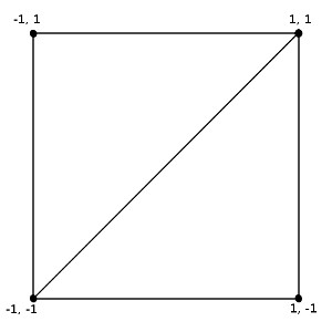 This quad is made up of two triangles. We render a texture completely over the quad. Once we load the texture with the desired image, the image will be rendered on the display. Let’s look at the steps in code. We have two shaders back.vsh and back.fsh that are responsible for rendering the texture over the quad. In the constructor of
 BackTexture, we begin with loading shaders and their associated variable locations:
shaderProgramID = LoadShaders("shaders/back.vsh", "shaders/back.fsh");
textureSamplerLocation = GetUniformLocation(shaderProgramID, "textureSampler");
vertexAttribute = GetAttributeLocation(shaderProgramID, "vertexPosition");
Then we create a VBO consisting of four vertices that represent the quad:
const GLfloat vertices[] = {-1.0f, 1.0f, -1.0f, -1.0f, 1.0f, 1.0f, 1.0f, -1.0f };
glGenBuffers(1, &vertexBuffer);
glBindBuffer(GL_ARRAY_BUFFER, vertexBuffer);
glBufferData(GL_ARRAY_BUFFER, sizeof(GLfloat) * 8, vertices, GL_STATIC_DRAW);
glBindBuffer(GL_ARRAY_BUFFER, 0);
Then we create a texture with required dimensions (width x height):
this->width = width;
this->height = height;
glGenTextures(1, &textureNameInGL);
glBindTexture(GL_TEXTURE_2D, textureNameInGL);
// specify linear filtering
glTexParameteri(GL_TEXTURE_2D, GL_TEXTURE_MAG_FILTER, GL_LINEAR);
glTexParameteri(GL_TEXTURE_2D, GL_TEXTURE_MIN_FILTER, GL_LINEAR);
// create an empty texture
glTexImage2D(GL_TEXTURE_2D, 0, GL_RGB, width, height, 0, GL_RGB, GL_UNSIGNED_BYTE, 0);
We update the contents of the texture in BackTexture::LoadBackImg by loading a OpenCV Mat into it:
bool BackTexture::LoadBackImg(cv::Mat backImage) {

    if(backImage.rows!=height || backImage.cols!=width) {
        MyLOGE("Image size does not match texture dims");
        return false;
    }

    // bind the texture
    glBindTexture(GL_TEXTURE_2D, textureNameInGL);
    // Update GLES texture with the OpenCV Mat
    glTexSubImage2D(GL_TEXTURE_2D, 0, 0, 0, width, height, GL_RGB, GL_UNSIGNED_BYTE,
                    backImage.data);
    CheckGLError("BackTexture::LoadBackImg");
    return true;
}
glTexSubImage2D can be used to update a portion of the texture though we update the complete texture in this case. In above function, we insist that size of the cv::Mat match the texture dimensions. We might get an error in GLES or a segmentation fault if we feed a smaller Mat image than required.
Before looking at BackTexture::Render, let us understand the vertex shader back.vsh:
attribute   vec2 vertexPosition;
varying     vec2 textureCoords;
const float EPS = 10e-3;

void main()
{
    // Z coordinate of gl_Position is chosen so that image lies at the back
    gl_Position     = vec4(vertexPosition.xy, 1.0 - EPS, 1.0);

    // vertexPosition range is [-1,1]. Convert to range [0,1] for reading texture
    textureCoords   = (vertexPosition + 1.) * 0.5;
}
The quad described above is defined by only its (x,y) coordinates in the constructor of BackTexture. We choose the Z coordinate of the quad so that it is rendered at the back. This will allow us to render other objects in front of it in a subsequent tutorial. Texture (u,v) coordinates are the same as vertex positions, with a transformation to the range to [0,1]. These are used in the fragment shader back.fsh to read the texture image:
precision mediump float; // required in GLSL ES 1.00

uniform sampler2D   textureSampler;
varying vec2        textureCoords;

void main()
{
	gl_FragColor.xyz = texture2D( textureSampler, textureCoords ).xyz;
}
In BackTexture::Render, we bind the texture and render the quad. Most of the function is familiar to us from previous posts, except the call to draw the quad:
glDrawArrays(GL_TRIANGLE_STRIP, 0, 4);
GL_TRIANGLE_STRIP indicates that the vertices defining the quad form a series of triangles or a triangle strip. It is an efficient way of representing two triangles which would have otherwise required us to specify six vertices or an extra index buffer.
We instantiate a variable of type BackTexture in CornerClass::PerformGLInits as we saw earlier. In CornerClass::Render, we render the camera image with highlighted feature points by first loading it into a GLES texture and then rendering it on the quad:
cameraMutex.try_lock();
if(newCameraImage) {
    back->LoadBackImg(cameraImageForBack);
}
newCameraImage = false;
cameraMutex.unlock();
back->Render();
An important note: We glossed over a subtle fact in the above discussion. The size of the texture in BackTexture must match the dimensions of image returned in camera preview callback, but this size need not match size of the GLES display! That is because a GLES shader does not care about the final size of the GLES display. It always renders to a square quad with each axis ranging from 0 to 1 as discussed previously. It is the responsibility of glViewport function to indicate the size of the display so that the GLES driver can appropriately stretch the image and display it. We have chosen the camera preview resolution to be 1280 x 720 but this need not match the display size in your device. You need to also account for size of status and navigation bars that further reduce the size of the device’s GLES display. Hence the camera image will be stretched to fit your device’s display and if the aspect ratio of the device’s GLES display is very different from 16:9 then the distortion will be evident in the rendered image. The size of the GLES display is determined in MyGLRenderer::onSurfaceChanged and passed to CornerClass::SetViewport through a JNI call. We can print the dimensions of device’s GLES display by logging it in either function. This concept is a crucial aspect of GLES and you should thoroughly understand it.